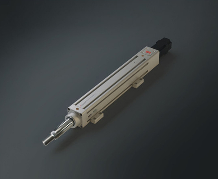
The electric cylinder can operate without faults in harsh environments and has a protection level of up to IP6. Long term work, achieving high intensity, high speed, high-precision positioning, smooth movement, and low noise. So it is widely used in the papermaking industry, chemical industry, automotive industry, electronics industry, mechanical automation industry, welding industry, etc.
Next, we will briefly introduce the control methods of servo electric cylinders.

1. Speed mode: The rotational speed can be controlled through the input of analog signals or the frequency of pulses. In the outer loop PID control with an upper control device, the speed mode can also be positioned, but the position signal of the motor or the position signal of the direct load must be fed back to the upper control for calculation purposes. The position mode also supports direct load outer ring detection of position signals. At this time, the encoder at the motor shaft end only detects the motor speed, and the position signal is provided by the direct final load end detection device. The advantage of this is that it can reduce errors in the intermediate transmission process and increase the positioning accuracy of the entire system.
2. Position control: The position control mode generally determines the rotational speed through the frequency of external input pulses, determines the rotation angle through the number of pulses, and some servos can directly assign values to speed and displacement through communication. Due to the strict control of speed and position, position mode is generally applied to positioning devices. Application areas such as CNC machine tools, printing machinery, etc.
3. Closed loop servo control: It is a closed-loop negative feedback PID regulation system, which is carried out internally by the servo driver. The output current of each phase to the motor is detected by the Hall device, and the negative feedback current is set for PID regulation to achieve the output current as close as possible to the set current.
4. Torque control: The torque control method is to set the size of the output torque of the motor shaft to the outside through the input of external analog signals or direct address assignment. For example, if 10V corresponds to 5Nm, when the external analog signal is set to 5V, the motor shaft output is 2.5Nm. If the motor shaft load is less than 2.5Nm, the motor rotates forward, and when the external load is equal to 2.5Nm, the motor does not rotate, When the torque is greater than 2.5Nm, the motor reverses (usually under gravity load). The torque size can be changed by instantly changing the analog setting, or by changing the corresponding address value through communication. The application is mainly in winding and unwinding devices that have strict requirements for material stress.
 +86 137 5504 3669


 jane.li@tiayofa.com


